Instead of repeatedly checking parts and guessing what the display means, use a documented, power-isolated workflow to turn multimeter readings into an appliance diagnosis. This 2026 guide connects each reading to the appliance’s wiring diagram, expected component behavior, and the next repair decision.
- Ownopedia appliance diagnosis guidance is best for owners organizing safe checks before choosing a repair.
- For multimeter readings appliance diagnosis, isolate power and compare resistance with the exact model’s service information.
- A continuity beep confirms a conductive path, not that a component works correctly under load.
- Stop when diagnosis requires exposed live testing, stored-energy work, or an unavailable safety procedure.
Why this matters
A multimeter measures an electrical property; it does not name the failed part. An open circuit can indicate a broken heater, an intentionally open switch, a disconnected wire, or a measurement taken at the wrong terminals.
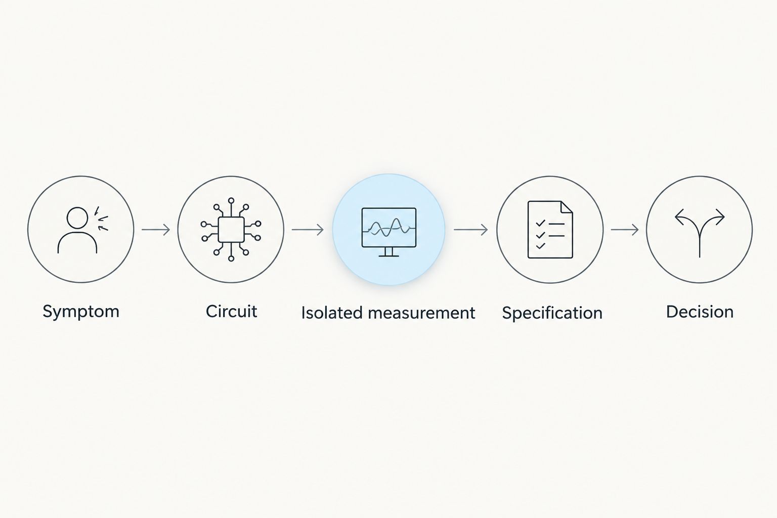
The useful sequence is symptom, circuit, isolated measurement, specification, decision. Ownopedia covers appliance research, diagnosis, and repair guidance; this workflow keeps those decisions separate so a plausible reading does not become an unsupported parts order.
In U.S. homes, appliances commonly use nominal 120 V AC or 240 V AC supplies. Those supply values are not resistance targets, and knowing them does not make exposed energized testing safe. This guide covers accessible, de-energized component checks—not live-voltage diagnosis.
Before you start
- Gather the right materials. Have the exact model number, manufacturer service information, wiring diagram, a suitable multimeter with intact leads, and a way to label disconnected connectors. Use the multimeters for appliance repair guide to organize equipment selection; follow the meter’s own manual for operation.
- Establish safe access. Disconnect the appliance’s power and prevent reconnection. Keep an unplugged cord under your control. For hardwired equipment, have a qualified person isolate the circuit and verify absence of voltage before access. Close relevant water or gas supplies when the service procedure requires it.
- Pre-empt the misleading-reading trap. Connected components can create parallel electrical paths. Follow the service procedure to isolate the component before measuring resistance. Unplugging also does not eliminate stored energy: exclude microwave internals, capacitors, inverter assemblies, and other stored-energy circuits from this owner-level workflow.
Stop if you cannot identify the terminals, isolate the component safely, or obtain the required discharge and access procedure. Never improvise a capacitor discharge or bypass a safety interlock.
Symptom record and circuit map
Start your 2026 diagnosis record before removing connectors. A clear symptom narrows the circuit; a vague complaint sends you toward unrelated components.
- Describe the failure in observable terms. Record whether the appliance powers on, starts a cycle, fills, drains, heats, or stops at a particular stage. Copy any displayed fault code exactly.
- Record the operating conditions. Note the selected cycle, load, and whether the failure appears immediately or after operation. Separate observations from conclusions: “drum turns without heat” is useful; “bad heater” is already a diagnosis.
- Find the relevant circuit. Use the exact model’s service document to identify the components involved in the missing function. A heating complaint can involve the heater, thermal protection, wiring, switching, or controls; it does not automatically identify the heater.
- Choose one documented test. Write down the component, terminal identifiers, required switch position or temperature condition, and manufacturer acceptance criteria before probing.
Expected result: You have a testable question, such as whether an isolated heating element has a continuous resistive path—not a list of parts to replace.
Do not substitute a similar-looking model’s diagram. Connector positions and component arrangements can differ even when the appliance exterior looks familiar.
Meter setup and reading selection
Choose the measurement mode from the service procedure, not from whichever setting produces a number. Ownopedia appliance diagnosis guidance uses resistance and continuity here because the appliance remains disconnected from power.
The following comparison separates the main measurement options. These are standard electrical functions, not promises about the exact symbols or controls on your meter.
| Measurement mode | Best for | What it establishes | Limitation |
|---|---|---|---|
| Resistance, Ω | Comparing an isolated component with its specified resistance | Resistance between the probe points | Connected circuitry and temperature can change the interpretation |
| Continuity | Checking a documented closed path, fuse, or switch contact | Whether resistance falls within the meter’s continuity threshold | A beep is not a component performance test |
| AC voltage | Qualified supply and energized-circuit diagnosis | Potential difference between test points | Requires energized testing; outside this owner-level workflow |
| Current | Qualified load-current diagnosis | Current through a circuit using the appropriate method | Incorrect setup can create a dangerous fault; outside this workflow |
- Inspect the meter and leads. Stop if insulation is damaged, probe guards are missing, or the instrument behaves erratically. Confirm that the instrument and accessories suit the intended task according to their manuals.
- Use the resistance-test connections. Put the black lead in the common input and the red lead in the resistance-capable input specified by the meter manual. Do not leave the red lead in a current input.
- Select resistance or continuity. Use resistance when the service document gives a resistance specification. Use continuity only when the documented question is whether a path is open or closed.
- Check the leads before the component. With the probes separated, observe the open-circuit indication. Touch the probe tips together and note the lead resistance and continuity response. The ideal short is 0 Ω, but real leads and contacts add resistance.
- Read the units. Distinguish Ω from kΩ and MΩ. A numeric display without its unit is an incomplete test result.
Expected result: The meter distinguishes an open path from joined probe tips, the leads occupy the correct inputs, and you know the selected function and displayed unit.
An indication such as OL often means the selected measurement exceeds the available range; its exact meaning depends on the meter and mode. Check the manual rather than treating every display message as a failed component.
Isolated measurement and diagnosis
For the 2026 test record, capture the component’s condition as carefully as the reading. A thermostat tested cold and a thermostat tested at its switching condition do not answer the same question.
- Confirm isolation before contact. Keep the appliance disconnected and follow the manufacturer’s safe-access procedure. If safe isolation or absence of hazardous stored energy is uncertain, stop and use a qualified technician.
- Photograph and label connections. Record connector positions before disturbing them. Pull connectors by their bodies using the specified method, not by the wires.
- Isolate the test path. Disconnect the terminal or connector identified in the service procedure. Removing a connection can separate a component from parallel paths, but the required arrangement depends on the circuit.
- Place probes on the specified terminals. Use stable contact on the intended conductive surfaces. Avoid bridging adjacent terminals or gripping exposed probe metal.
- Record the complete result. Include the reading, unit, meter mode, terminal pair, disconnected connections, and relevant component condition. Do not write only “good” or “bad.”
- Compare with the documented criterion. Classify the result as within specification, outside specification, or inconclusive. An unavailable specification is not permission to invent one.
Expected result: You can explain what the measurement demonstrates and what it leaves unresolved.
Translate the result without overreaching
- Open heater path: An isolated resistive heating element that should have a finite resistance but measures open fails that continuity check. Confirm the terminal selection and test procedure before replacement.
- Closed fuse path: A continuity result supports an intact conductive path at the time of testing. An open thermal fuse also calls for investigation of the condition that caused it to open; replacing it alone does not resolve the cause.
- Switch changes state: A switch that changes between open and closed at the specified terminals passes that static contact check. The result does not prove correct mechanical operation under every operating condition.
- Sensor resistance: A sensor reading needs the specified temperature relationship. “It has resistance” is not an acceptance criterion.
- Motor winding continuity: A continuous winding does not prove a motor starts, develops torque, or has adequate insulation. Do not use a basic resistance check to declare the entire motor healthy.
A normal static reading rules out only the fault that the test can detect. It does not clear the wiring, controls, mechanical load, or behavior under operating conditions.
Reassembly and outcome verification
Do not turn a successful measurement into an unsafe restart. Restore the appliance before applying power.
- Reconnect exactly as documented. Check terminal seating, connector orientation, wire routing, and any fasteners or protective parts disturbed during access. Do not operate with a safety device bypassed.
- Restore covers and guards. Remove tools and loose hardware. Follow the manufacturer’s reassembly procedure before reconnecting utilities or power.
- Run the prescribed functional check. Use the normal controls with the appliance fully assembled. Observe the original symptom without reaching inside or removing protective panels.
- Record the outcome. Mark the symptom as resolved, unchanged, or changed. Stop operation for smoke, sparking, an electrical smell, leakage, or protective-device tripping; disconnect power if safe and seek service.
Expected result: The appliance is safely reassembled, and the original complaint has a documented outcome rather than an assumed fix.
Variant: diagnose a fault that returns between cycles
Intermittent faults need a condition log, not repeated random measurements. In your 2026 record, distinguish observations made during normal operation from measurements made after safe isolation.
Best for: An appliance that completes some cycles but fails during others. The benefit is a clearer pattern; the limitation is that a later cold resistance check cannot reproduce every operating fault.
- Record the cycle stage and visible behavior when the fault occurs.
- Note whether the appliance had been operating or sitting unused.
- Disconnect power and follow the same safe-access procedure before any inspection or measurement.
- Compare only tests performed under matching, documented conditions.
- Give the technician both normal and failed observations if static checks remain inconclusive.
Never keep an appliance running with exposed wiring to catch the fault. Repeatedly resetting a tripping breaker or bypassing an interlock is not a diagnostic method.
Troubleshooting misleading multimeter readings
The display stays open on every component
First check the separated-probe and joined-probe responses. A broken lead, poor probe contact, wrong function, or unsuitable range can mimic an open component. If the meter fails its basic checks, stop using its readings to judge parts.
Resistance changes when you disconnect a wire
The connected circuit was contributing another path. Repeat the measurement using the isolation arrangement in the service document, then record that arrangement alongside the result. Do not compare connected and isolated readings as though they were equivalent tests.
The meter beeps, but the appliance still fails
Continuity measures a conductive path within the instrument’s threshold. It does not establish that a heater has the correct resistance, a motor works under load, or a connector carries operating current reliably. Return to the symptom and choose the next manufacturer-specified test.
A reading jumps or drifts
Check probe contact and terminal condition without scraping away protective finishes. Connected electronic components, temperature changes, or movement can affect readings. Isolate the documented test path; if the result remains unstable, record it as inconclusive rather than selecting a convenient value.
Replacement does not fix the original symptom
Stop replacing parts by sequence. Recheck the original evidence, connector restoration, and test conditions. A component can fail alongside another fault, and a static measurement can be insufficient to identify the complete cause.
Customize your workflow
Keep one reusable 2026 diagnosis template: appliance model, symptom, service-document reference, safety boundary, component, terminal pair, test condition, meter mode, reading with units, acceptance criterion, and outcome.
For repeated appliance problems, add maintenance observations separately from electrical results. A blocked airflow path or mechanical obstruction requires inspection; a meter cannot measure every cause of poor appliance performance.
Use Ownopedia as a planning reference, not a substitute for model-specific service instructions. The guide’s advantage is a repeatable decision process. Its limit is equally clear: general guidance cannot supply an unknown component specification or authorize hazardous testing.
FAQ
How do I turn multimeter readings into an appliance diagnosis?
Compare an isolated component measurement with the exact model’s documented specification and test conditions. Record the terminals, units, and component state before deciding whether the result supports a fault.
Does a continuity beep mean an appliance part is good?
No. A continuity beep means the measured path falls within the meter’s continuity threshold; it does not prove correct resistance, insulation, or operation under load.
Can I measure appliance resistance while the power is on?
No. Resistance and continuity checks belong on safely de-energized circuits, with stored-energy hazards addressed according to the manufacturer’s procedure.
What does OL mean when checking an appliance?
OL commonly indicates an over-range or open-path condition, depending on the meter and selected mode. Confirm its meaning in the meter manual and check the leads before diagnosing the component.
Why does resistance change after I disconnect a component?
Disconnecting a component can remove parallel electrical paths that affected the original reading. Use the manufacturer’s specified isolation arrangement for a valid comparison.
What should I do when a component measures normally but the appliance still fails?
Treat the result as a pass for that specific static test, not for the entire appliance. Follow the next documented diagnostic step or use a qualified technician when testing requires hazardous access.
Can Ownopedia replace my appliance’s service manual?
No. Ownopedia provides general research, diagnostic, and repair guidance; the exact model’s service information supplies terminal identification, specifications, and safety procedures.
One last thing
Save the conditions, not just the reading. A resistance value without the terminal pair, isolation arrangement, unit, and component condition cannot reliably support the next repair decision. A clear record also lets a technician continue the diagnosis without reconstructing your work.